|
|
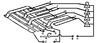
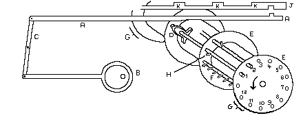
The Carter machine, as it is now, represents the culmination of
35 years of development. During this period the mechanism for
striking the bells changed somewhat; early versions used a machanical
striking mechanism, with a group of bowl-shaped bells mounted
above the machine. It appears that the sound of this was not
satisfactory and Carter replaced this with an electrical arrangement
and connected up a group of what appear to be handbells, but with a
striker operated by electromagnet for each bell. The machine, therefore
outputs electrical pulses over twelve wires to this arrangement.
In order to strike the bells in sequence, the machine has a distributor.
This consists of a paxolin panel with rings of brass studs, arranged
in rings of 5, 6, 7, 8, 10, 12 so that peals can be rung on groups
of these many of the bells. In fact, the rings contain twice the
above numbers, one revolution being equivalent to a backstroke
followed by a handstroke. A slightly larger gap gives a slight
pause between the pairs of rows.
The distributor, therefore, produces a series of short pulses on
a subset of the 12 wires which are connected to the studs.
In order to get the bells to ring in different sequences a
switching arrangement is provided which can connect any of the
bells to any of these wires.
|
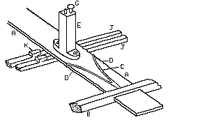
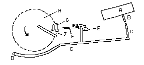
Brian Price used a diagram like this to illustrate the idea.
This is actually quite different in layout to that used
on the Carter Machine, but illustrates the general principle. |
|
In this diagram the bars A, B, C and D are connected to the
distributor, while bars E, F, G and H are connected to the
bells. Springy brass sliders J, K, L and M make connections
between the two sets of bars. Provided each slider connects
a different pair of bars, the bells will operate in some order
depending on the positions of the sliders. In the position shown
in the diagram the order will be E, G, F and H.
The Upper Frame of the Machine
|
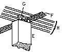
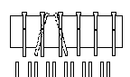
In the carter machine the strips of springy brass are replaced by
steel bars (A) mounted in a frame (B).
Each one represents a bell and are therefore known as 'bell-plates'.
Each bell-plate has a pillar (E) on the top of which are two contacts (G).
This drawing shows one of the bell-plates, looking down at an angle.
|
|
|
Above the bell-plates, which are mounted across the frame,
there is a longitudinal
panel which has twelve contact wires (H) along its length,
and twelve transverse bars (F). The mushroom-shaped contact runs across
the wires, while the stud-shaped contact runs along the bars.
This drawing shows the contacts viewed from below: |
|
The longitudinal wires carry the current from the distributor and
the transverse bars are connected, by wires above the panel, to the
bells. The two contacts (G) are sprung inside the pillar and are
also connected together, thereby providing the connection between
the distributor and the bells.
|
The bell-plates (A) can slide across the frame, but each is gripped by a
springy clamp (C) which prevents unintentional movement. The edges
of the plate are serrated with twelve notches for each of the
positions that the bell can hold. The twelve positions that the
plate can assume correspond to the places in a row that the bell
can take up.
These bell-plates are moved by longitudinal bars (J), know as the
pre-selection bars.
There are eleven of these bars running side-by-side along the length
of the frame.
Each bar can cause two adjacent bell-plates to exchange
positions as follows:
|
On the underside of each bell-plate, there are two oddly-shaped levers (L).
The pre-selection bars (J) have small lugs (K) on the upper side. These
can engage with the levers, and as the rod moves forward,
the lever tilts and pushes the plate sideways.
A spring (N) causes the levers to return to the normal position when
the pre-selection rod returns to its home position. |
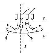 |
It will be noticed
that only one of these levers should engage with a rod, otherwise the
mechanism will jam!
All of the above are contained within a rigid frame that is removeable.
This provides access to the mechanisms below which we come to below.
If you look at the
photographs
of the machine,
several of these have this upper section removed. |
To summarise the above: we have a switching mechanism that, in any of
the valid positions, will produce a sequence of strikes, in some order
for every half-revolution of the distributor. A series of pre-selection
rods, running the length of the upper frame, can cause any two adjacent
bells to change places. These rods are identified by the positions that
they control, thus rod 1-2 causes the bells in first and second place to
swap, 2-3 the bells in second and third place, and so on down to 11-12.
It will be seen that eleven rods are sufficient to control the twelve
bells. The only constraint is that two adjacent rods must never operate
at the same time!
During setting up of the machine, the bell-plates can be moved by hand.
It is obviously important to ensure that each plate holds its correct
position before starting, otherwise the sequence will be incorrect.
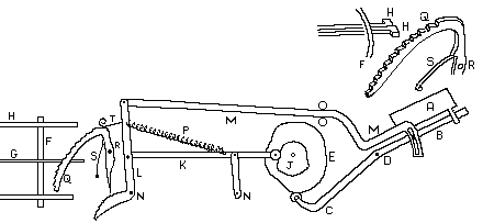
The Lower Frame
The lower part of the machine is concerned with controlling the
sequences of strikes for each row.
The machine is operated by an electric motor in the box which acts
as a stand for the machine. In addition to the motor, there is a
speed control mechanism, and a transformer and rectifier to provide
electrical power to operate the bells.
Power is transmitted from the base to the lower frame via cog-wheels.
The wheel on the main spindle is fitted with a friction clutch so that,
in the event of the mechanism jamming, the clutch will slip and avoid
damage to the more delicate parts of the mechanism.
The main shaft passes through the centre of a 'squirrel cage' drum
which consists of four disks (E), and thirteen rods. Twelve of these
rods can move a short distance from side-to-side and carry cams (D)
and pins(H). The other rod is fixed and carries twelve further pins (F).
|
Above the drum are 11 actuator rods (A),
which are driven in a back-and-forwards manner by eccentrics (B) and
return levers (C). At the end of each actuating lever is a peg which
can engage in a slot in the bottom of the pre-selection levers (J).
This will only happen, however, if the actuator rod is lifted by the
cam at the appropriate position in the cycle. Normally, the cams lie
in between the actuating rods and do not lift them. If the bell-plates
are in the normal starting position, the bells will ring rounds.
|
|
In order for changes to be rung, the appropriate cams must be moved
under the corresponding actuating rods before the drum reaches the
position where the rods need to be lifted.
|
This is achieved by the control mechanism.
This consists of two boxes (A) of programming pegs (B), levers (C) and
rotating scoops (G). If the lever C is pressed down by a peg, it pulls
down on the cross-bar (E), which rotates shaft (F) and the scoop (G).
When the pin on the shaft (J) passes the scoop, it will be moved left
or right depending upon which way the scoop has been rotated.
|
|
|
The programming box is simply a frame to hold 15 rows of 6 programming
pegs. These pegs are pivoted about a centre point and can be either
vertical, inclined left or inclined right. In the vertical position
they do not engage with any of the levers, if they are inclined to
one side, they engage the appropriate lever when the box is lowered.
|
|
By moving the box to an appropriate position, any one of the rows of
pegs can be caused to line up with the levers, thus allowing the
operator to provide 15 different combinations.
One point which has perhaps not been stressed so far is that there are
two programming boxes, two sets of levers, etc. The front mechanisms
are used to control the backstroke, while the rear mechanisms control
the handstroke. This means that there are thirty different combinations
possible, but with restrictions to which stroke they are applied.
Finally, we move on to discuss how these combinations are selected.
At the opposite end of the machine from the programming boxes, there
are two drums, again, one for backstroke, the other for handstroke.
These consist of circular frames (F), surrounded by a series of sequence
bars (H). The bars are held within the frames, but can move laterally,
but are restrained by a spring (not shown) which surrounds them and so
prevents unintentional movement. These bars are moved to appropriate
positions during the setting-up of the machine.
|
The drums rotate slightly after each round has occurred, bringing a
different bar to the top. A curiously-shaped lever (Q), operated by a
cam (J) on the main shaft, rises until it is prevented from going further
by coming into contact with the current bar. The lower end of the lever
engages in a ratchet at the bottom of lever (L) and prevents its
complete return. The position at which this happens is therefore
controlled by the position of the corresponding sequence bar.
|
|
Linked to level (L) is a long bar (M) which engages with a stud
projecting from the programming box (A). The box in turn slides
along lever (B) which, via a pivot at (D) is operated by another
cam (E) on the main shaft. The programming box, therefore lifts
up and down and slides out along (B) as the cams (J) and (E)
rotate. Provided the sequence bars have been positioned correctly,
the programming box will depress the selected control levers,
operate the sliding rods, the cams (D) on these rods will lift the
actuating bars, which will cause the specifed changes to be made.
Each of the programming drums is mounted on a shaft which, as has
already been stated, rotates slightly for each row of the peal.
This is achieved by a ratchet, also operated by a cam on the main
shaft. Each shaft has a control dial, which can be set to any number
from 0 to 48. When the drum has rotated by the number selected a
release is triggered and the drum spins back under pressure from
a spring to the zero position. Thus the machine can cycle through
the prescribed sequence of changes, then repeat them.
This takes care of the large proportion of the changes. In order
to complete a peal, however requires additional changes. These are
produced manually by a two buttons provided. These cause the
programming box to select two additional changes at these points.
Acknowlegements
I owe a big thank-you to Alan Bagworth and John Anderson, the then
Stewards of the machine, for inviting me to join them as they
prepared the machine for a demonstration. Also to Bob Bracegirdle,
the Museum Curator, for providing initial information.
I also owe a debt to Brian Price, for the articles he wrote in Ringing
World in 1950, which have provided me with a reference description
to base this page upon.
By Bill Purvis - 12th October 2010
|